Retrofitting RLS T2 WS
The installation of the CDV commissioning software is required to use the RLS T2 WS. For software download and further information, see chapter Commissioning the WS.../Trio installation and commissioning instructions.

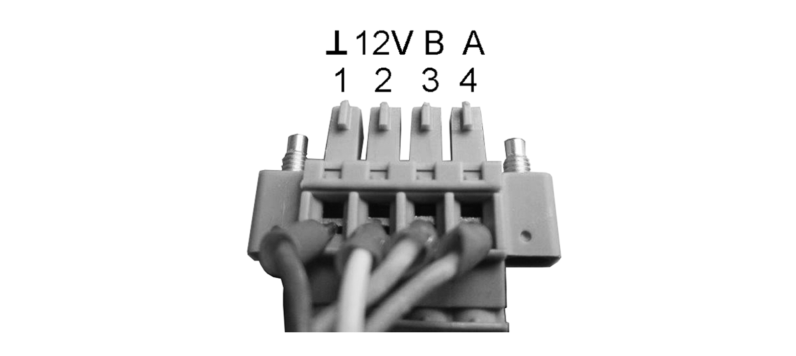
 Be sure to note the writing on the control unit and control circuit board. Only connect as shown in the enclosed wiring diagram.
Recommended installation position of the room temperature sensor (bottom side of the RLS T2 WS)
- Installation height approx. 1.5 m
- Not in direct sunlight
- Not above sources of heat
- Not in cold draughts (doors, windows)
Preparations for installation, to be made by customer
- De-energise the ventilation unit and secure it against being switched on again.
- Flush-mounted box at installation location.
- Route connection cables at installation location. Permitted: Shielded control cable, e.g. LIYY 4 x 0.34 mm².
Fitting control unit at installation location
- Fit supplied mounting plate on flush-mounted box.
- Wire supplied connector plug.
- Attach the control unit (steps ① to ③) → Wiring diagrams.
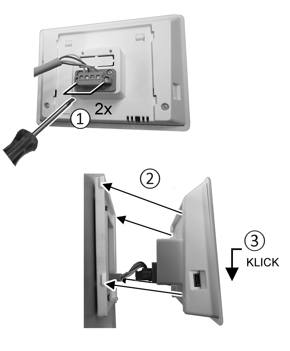
- Plug connector plug into control unit and screw in.
- Push the control unit onto the mounting plate and snap it into place.
- Check the functions on the control unit.
Lead the connection lines into the ventilation unit and wire them electrically
- Remove front cover of ventilation unit.
- Depending on the unit type, remove the screw on the electronics slide-in module and lift the electronics slide-in module, pull it out of the electronics compartment and hook it into the securing groove of the ventilation unit frame.
 NOTICE If the connection cables are too short, the electronics slide-in module cannot be fully pulled out/fitted.
Ensure connection cables of a sufficient length inside the ventilation unit.
DANGER Danger of short circuit/fire if moisture penetrates into the terminal compartment. If installed incorrectly, the electronics compartment is not sealed.
Short circuits and fire can lead to serious injuries with fatal consequences.
Ensure correct, tight line feedthrough through the cable feedthrough and membrane grommet with slot.
- Ensure correct, tight line feedthrough the cable feedthrough.

- Correctly push through cable feedthrough.
- Guide connection cable through cable feedthrough into ventilation unit.
- Check for leaks and remedy any found.
Only guide connection cable individually through the cable feedthrough. Feedthroughs which are not needed must remain sealed.
- Wire cables electrically on the control circuit board A2, terminal block X11 (RS 485), according to the wiring diagram of the ventilation unit → Wiring diagrams.
- Push the electronics slide-in module into the electronics compartment and screw it tight.
- Attaching front cover.
- Switch on the mains fuse, the ventilation unit switches on.
- Use the Commissioning software to set the Basic settings / Comfort control unit parameter to RLS T2 WS.
- Test settings and functions.